Tech Tips: Torque Rod Replacement...
by Jim Hallman and Paul Vargyas
It's a love/hate relationship. Either you love the expansive and expensive Fiero GT rear
wing, or you hate it! If you are one of the ones who love it, and your Fiero does not have
it, you are undoubtedly seeking to find one.
However, once you find your wing, proper installation is more than just a bolt-on process
because the rear torque rods that keep the deck lid from crashing down on your head may
not be the correct ones for your old deck lid with your new wing. Quite simply, torque
rods are lengths of twisted steel rod that create enough tension to counter balance the
weight of the deck lid to hold it open. Adding a rear wing to a Fiero that did not
previously have one adds about 10 pounds to the top, rearward end of the deck lid. Thus
the need for a larger torque rod to counterbalance the added weight.
The Pontiac Fiero came with three different torque rods. Fiero's equipped with a luggage
rack had a torque rod with a light spray of blue paint on the "U" shaped ends
(GM part numbers: 20355089-left hand side & 20355088-right hand side). Fiero's
equipped with the GT wing had a torque rod with a light spray of white paint on the
"U" shaped ends (GM part numbers: 20380985-left hand side & 20380984-right
hand side). Fiero's equipped with a plain deck lid had a torque rod with a light spray of
red paint on the "U" shaped ends. Each of these three torque rods has a
different diameter rod to offset the various weights of the individual option added to the
deck lid. Thus, if your Fiero has a plain deck lid (red paint on the "U" shaped
ends) and you add a rear wing to it, you need a torque rod with white paint on the
"U" shaped ends in order for your deck lid to stay up when it is opened. If you
do not change the torque rods when you add the rear wing, your deck lid will not stay up -
unless you use a prop rod. Even increasing the 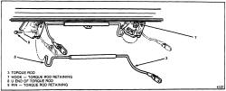 rod's tension by moving the torque rod retaining pin forward a
notch (see step #7) will not keep your deck lid from falling down. You can determine if
your car was originally equipped with a luggage rack or wing by looking at the three digit
"RPO" codes located on the sticker on the inner front left fender next to the
brake reservoir. D80 means your Fiero was equipped with the Fiero wing (you should have
"white" painted on the bars. V56 or V58 means your Fiero was equipped with the
luggage rack (you should have "blue" painted on the bars.
rod's tension by moving the torque rod retaining pin forward a
notch (see step #7) will not keep your deck lid from falling down. You can determine if
your car was originally equipped with a luggage rack or wing by looking at the three digit
"RPO" codes located on the sticker on the inner front left fender next to the
brake reservoir. D80 means your Fiero was equipped with the Fiero wing (you should have
"white" painted on the bars. V56 or V58 means your Fiero was equipped with the
luggage rack (you should have "blue" painted on the bars.
Before proceeding any further, words of great caution must be expressed. If not done
cautiously, this replacement procedure could easily shatter your rear window or break your
fingers. This procedure is a two person project at a minimum. With this out of the way,
let's proceed:
-
Disconnect the wiring harness located near the battery that supplies power to the deck lid lock solenoid from the deck lid (if equipped).
-
Disconnect the radio static grounding wire on the air cleaner side of the deck lid (if equipped).
-
Mark the orientation of the deck lid to the hinges using tape, a marker, etching device, etc. to allow for proper alignment of the deck lid upon re-installation.
-
Remove the deck lid by removing the two bolts on each side that hold the deck lid to the hinges using a 13MM socket.
-
Tape large squares of wood onto the rear window glass just behind the hinges as a precaution to prevent the deck lid hinges from smashing through the glass as tension is released from the hinges.
-
Mark the orientation of the hinge bolts to the hinge using paint, an etching device, etc. to allow for proper alignment of the hinges to the hinge support bracket upon re-installation.
-
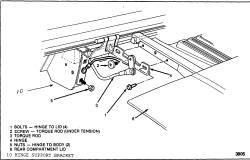
Notice the shape of the torque rods. The torque rods have squared off open loop ("U" shaped) end's on the opposite end of the hinge linkage. This "U" end goes underneath and in between the sides of the hinge support bracket and rests against the torque rod retaining pin that passes through the hinge support bracket. Three rates of tension can be created using the three hole settings on each bracket to vary the tension rates of the rods. Normally, this solid pin is in the middle of the three holes. This pin needs to be removed to release most of the tension created in the torque rod. This can be done using nylon rope that is looped around the bottom of the loop at the "U" end of the torque rod. . We have found that the person who will be pulling the rope rearward to release the tension should wear gloves to protect their hands and wrap the rope securely around each hand. Then, place one foot against the forward trunk well for leverage as you pull rearward to release the tension of the rod in order to remove the pin. Start by removing the driver's side pin. With your assistant firmly pulling the rope towards the rear of the car, the torque rod "U" end will begin to be pulled rearward to allow the pin to be pulled out from the hinge support bracket Be very cautious with this step - for if the rope slips and your fingers are in the way, the tension of the torque rod will smash your fingers into the firewall. Make certain your partner has a firm, steady grip on the rope before you move your fingers in place to remove the pin. Once the pin is pulled out, slowly release the hold on the rope to gently allow the torque rod to rest against the firewall.
-
Follow the same steps that are in #7 to remove the torque rod retaining pin from the passenger's side.
-
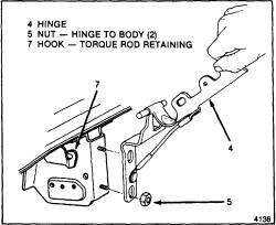
Please be aware that there is still quite a bit of tension built up in the torque rods even though the pins have been removed. The next step is to remove the deck lid hinges with the torque rods still connected to them, as a unit. Begin by loosening the lower nut holding the hinge to the hinge support bracket on the passenger's side using a 13MM socket. Do not remove the lower nut entirely, just loosen it a few turns at this time. Next, loosen the upper nut holding the hinge to the hinge support bracket using a 13MM socket. Slowly loosen this upper nut all the way to remove it - be aware that tension is being released as you slowly loosen these nuts.
-
Now that the upper nut has been removed, the lower nut now needs to be removed. Slowly remove the lower nut holding the hinge to the hinge support bracket. Be careful because once this nut is removed, the tension will be fully released from this rod - keep hands clear from the hinge to prevent injury.
-
The torque rod is held in position in two places. The first place is on the side of the hinge support bracket where a "C" shaped hook holds the torque rod in place. The second place is on the opposite end of the torque rod where it slides behind a lip on the hinge support bracket. Once the nuts holding the hinge in place have been removed, work the torque rod free from these two points to remove the torque rod from the Fiero. NOTE: you may need to use a screwdriver to pry the torque rod out of the "C" hook if the tolerance is too close. Once removed, label this torque rod "#1 Passenger Side" and set aside. Notice that this torque rod has a rubber cushioning sleeve wrapped around it to prevent it from rubbing with the other torque rod.
-
Repeat steps 9, 10, and 11 to remove the torque rod connected to the driver's side hinge. Once removed, label this one "#2 Driver Side" and set aside.
-
Looking at the torque rod/hinge assemblies you just removed, notice the Torx bit screw head which holds the torque rod to the hinge. The bit needed to remove this screw is a special theft deterrent bit because it has a center piece to prevent using a standard Torx bit to remove it. These special Torx bits are available from your local Trak Auto parts store - other parts stores should have them as well. The part number for this seven piece set is #26000 from Lisle Corp. and cost about $12.99. Using the #T-40 size bit, loosen the bolt securing the torque rod from the hinges on both the #1 and #2 rods. If you want to, repaint the hinges and torque rods for that "new, factory" look.
-
Match up the new torque rods with the old torque rods labeled #1 and #2 to make sure you are installing the correct bar to the correct hinge. Apply grease to the contact points where the screw holds the torque rods to the hinge to prevent wearing.
-
It would also be recommended to apply grease to the contact points that hold the torque rods in place - both the "C" hook and the lip that are both located on the sides of the hinge support brackets.
-
We are now ready for the re-installation of the torque rod/hinge assemblies. The first assembly to re- install is the one labeled "#2 Driver Side" (because this one was the last one removed). This step requires two people. First, position the assembly so that the torque rod fits into the "C" hook on the passenger side hinge support bracket making sure the hinge aligns up with the screws in the hinge support bracket while aligning the torque rod to fit behind the lip on the driver's side hinge support bracket - and at the same time, aligning the "U" loop on the end of the torque rod up and in between the sides of the driver's side hinge support bracket. This step is as complicated and difficult as it sounds because you are trying to align four things at the same time.
-
While having your assistant tightly hold the torque rod in position, pull down firmly on the deck lid hinge to align the hinge with the hinge support screws. Position the hinge in place so you can screw on the lower retaining nut to hold the hinge in position. Tighten this nut down making sure it aligns with the marks you placed on the hinge when you removed the retaining nuts. Be careful and hold firmly because you are now building tension in the torque rod. With the alignment correct, re-install the upper retaining nut and then tighten both nuts securely. Verify the torque rod is correctly positioned.
-
Now you are ready to install the "#1 Passenger Side" torque rod. Follow the same steps in #16 and #17 as you did for the "#2 Driver Side" torque rod.
-
Verify the torque rods are seated in the "C" hook and up in back of the lips on the hinge support brackets. Verify that the four hinge nuts are securely tightened. We are now ready to add more tension to the rods by setting the torque rods on the pins. Generally, a good place to insert the torque rod pins is in the middle hole of the three located on the hinge support brackets.
-
Review step #7. This step requires two people. Loop the nylon rope around the bottom of the "U" end of the torque rod on the passenger side. Have your assistant pull firmly back on the torque rod until you can insert the pin into the middle hole on the side of the hinge support bracket.. Insert the pin and cautiously release the rope's tension to allow the torque rod to rest on the pin. Be very cautious with this step - for if the rope slips and your fingers are in the way, the tension of the torque rod will smash your fingers into the rear firewall.
-
Repeat step #20 for the driver's side pin insertion.
-
You are now ready to re-place your deck lid. Make sure you properly aligned the deck lid with the hinges using the alignment marks you have made on the deck lid. Re-install the four bolts which secure the deck lid to the hinges - two on each side.
-
Re-connect the radio static grounding wire located on the air cleaner side of the deck lid.
-
Re-connect the wiring harness for the power deck lid lock solenoid on the battery side of the deck lid (if equipped).
-
Slowly lower the deck lid to test the newly installed torque rods and make sure the deck lid is properly aligned with the rest of the body panels.
-
If you were successful, your deck lid will stay up all by itself as you raise it - no more prop rods, no more lumps on your head. Enjoy!